Cisco UCS: AWS-compatible cloud at the edge
Place EC2 instances, EBS volumes, S3 object storage and Kubernetes workloads on a resilient three-node Cisco UCS cluster, using familiar AWS APIs and tooling.
Overview
This reference architecture turns three Cisco Unified Edge servers into a small, resilient cloud that can run where data is produced: a factory, retail estate, branch, lab, sovereign environment, or disconnected site. Spinifex exposes EC2, EBS, S3 and EKS-compatible APIs on the cluster, so the operational model is familiar: use the AWS CLI, SDKs, Terraform or OpenTofu, Kubernetes manifests and CI/CD systems already used for AWS. The change is the endpoint, not the workflow.
Companion architectures: Vision Pipeline on Cisco UCS shows a local AI pipeline that streams inputs from S3; vLLM Serving on Cisco UCS shows CPU and GPU model serving on the same cluster.
Platform
| Component | Specification |
|---|---|
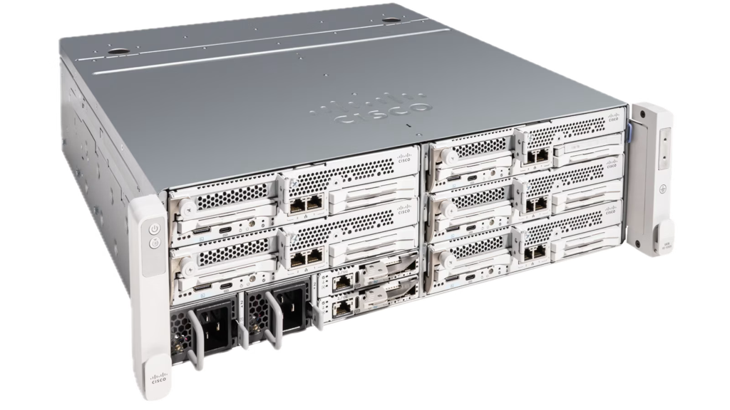
| Chassis | 3× Cisco Unified Edge, single-socket each |
| CPU | 1× Intel Xeon 6543P-B per node — 32 cores / 64 threads, 800 MHz–3.30 GHz |
| Cache / NUMA | L3 128 MB (unified), single NUMA node — no vCPU/memory locality tuning needed |
| ISA | AVX-512 (F/DQ/BW/VL/VNNI/BF16/FP16), Intel AMX (tile/BF16/INT8), VT-x, VT-d |
| Memory | 499 GiB usable per node (≈1.5 TiB aggregate) |
| GPU | 1× NVIDIA L4 (23,034 MiB) via VFIO PCIe passthrough on one node; the other two nodes are CPU-only |
| Storage | 4× KIOXIA CD8P NVMe (1.92 TB each) per node, raw — Predastore and Viperblock claim these directly |
| Boot | Cisco SATA RAID VD (Marvell 88SE9230 controller) |
| Network | 2× Intel E825-C 25GbE ports per node — one bond for management/WAN (VLAN 1337), one dedicated to storage/cluster traffic (VLAN 1336, full 25GbE) |
| Aggregate | 96 cores / 192 threads, ~1.5 TiB RAM, ~23 TiB raw NVMe, 1× L4 GPU |
Single-NUMA-per-node simplifies placement — no vCPU/memory locality tuning required. GPU workloads schedule to the L4 node; CPU instances can use all three. Storage and object data are distributed across the cluster rather than tied to the node that launched an instance.
Hardware Chassis
Architecture
AWS services exercised
| Service | Role |
|---|---|
| EC2 | Guest instances across all three nodes; spread placement groups distribute across physical nodes |
| EBS (Viperblock) | Root and data volumes per instance, surviving termination independently when delete_on_termination = false |
| S3 (Predastore) | Cluster-wide object storage for datasets, model weights, artifacts and backups |
| VPC (OVN) | Overlay networking between instances |
| EKS | (Optional) Kubernetes control plane with pod rescheduling on node failure |
Prerequisites
- 3-node Spinifex cluster installed and services healthy on all nodes — follow the Multi-Node Install guide.
- VPC, subnet, network address pool, SSH key pair, and security group configured — see VPC Networking and Launching Instances.
- GPU passthrough enabled on the L4 node when GPU instances are required — see GPU Passthrough:
sudo spx admin gpu setup   # reboot required after this step
sudo spx admin gpu enable- AWS CLI configured with
AWS_PROFILE=spinifexpointing at the cluster's EC2-compatible endpoint (https://<host>:9999).
Instructions
1. Verify the cluster and its control plane
Before placing workloads, confirm all three nodes are ready and that the storage and control-plane services are running on each:
spx get nodes
systemctl is-active spinifex-predastore spinifex-viperblock spinifex-daemon
Predastore's Raft group and OVN's northbound/southbound databases are both distributed across all three nodes — losing one node triggers a clean leader re-election among the remaining two, and object storage and networking continue serving. Check that all three nodes are contributing to the Raft group before exposing the cluster to workload traffic.
2. Launch instances through the EC2-compatible API
Point an existing AWS profile at the Spinifex endpoint and use the standard EC2 instance lifecycle. Terraform is the recommended path — Spinifex's spread placement group implementation holds node reservations that are not always released on destroy, so a fixed group name can cause a subsequent apply to hang. Using a per-deploy unique name (via random_id or equivalent) avoids this:
resource "random_id" "suffix" {
  byte_length = 4
}

resource "aws_placement_group" "spread" {
  name     = "edge-spread-${random_id.suffix.hex}"
  strategy = "spread"
}

resource "aws_instance" "worker" {
  count                  = 2
  ami                    = var.ami_id
  instance_type          = "m8i.2xlarge"
  subnet_id              = var.subnet_id
  key_name               = var.key_name
  placement_group        = aws_placement_group.spread.name
  vpc_security_group_ids = [var.security_group_id]
}
For a one-off launch via the CLI, use a unique group name each time for the same reason:
export AWS_PROFILE=spinifex
GROUP="edge-spread-$(openssl rand -hex 4)"

aws ec2 create-placement-group \
  --group-name "$GROUP" \
  --strategy spread

aws ec2 run-instances \
  --image-id "$AMI" --instance-type m8i.2xlarge \
  --count 2 \
  --subnet-id "$SUBNET" --security-group-ids "$SECURITY_GROUP" \
  --key-name "$KEY_NAME" \
  --placement "{\"GroupName\":\"$GROUP\"}"
A g6.2xlarge instance type routes to the node with GPU passthrough configured; m8i types schedule across all three nodes.
3. Attach Viperblock volumes and access Predastore object storage
Create and attach an EBS-compatible data volume to a running instance:
VOLUME_ID=$(aws ec2 create-volume \
  --availability-zone "$AZ" \
  --size 100 --volume-type gp2 \
  --query VolumeId --output text)

aws ec2 attach-volume \
  --volume-id "$VOLUME_ID" \
  --instance-id "$INSTANCE_ID" \
  --device /dev/sdf
Setting delete_on_termination = false in Terraform keeps the volume alive across instance replacement — relaunching a terminated instance re-attaches the same volume rather than starting from empty storage:
resource "aws_ebs_volume" "data" {
  availability_zone = var.az
  size              = 100
  type              = "gp2"
}

resource "aws_volume_attachment" "data" {
  device_name           = "/dev/sdf"
  volume_id             = aws_ebs_volume.data.id
  instance_id           = aws_instance.worker[0].id
  delete_on_termination = false
}
Predastore presents an S3-compatible endpoint — standard S3 tooling works without modification:
aws s3 mb s3://my-bucket
aws s3 cp ./dataset.tar.gz s3://my-bucket/
aws s3 sync ./results/ s3://my-bucket/results/
All three nodes share the same bucket over the cluster's internal storage fabric, so datasets, model weights and pipeline outputs are accessible to any instance without mounting a shared filesystem.
4. Optional: deploy Kubernetes workloads through the EKS-compatible API
Spinifex also exposes an EKS-compatible control plane — this was not part of the Cisco exercise documented here, which used EC2, EBS and S3 directly. For workloads where automatic pod rescheduling matters, Spinifex supports the same kubectl workflows as a standard EKS cluster:
kubectl get nodes
kubectl apply -f deployment.yaml
kubectl get pods -n default
Kubernetes pod rescheduling is the platform's primary answer to node failure for scheduled workloads. The companion vision pipeline and vLLM serving architectures use raw EC2 instances; EKS is the pattern to reach for when automatic rescheduling matters over manual placement.
5. Storage benchmark
Predastore and Viperblock — Spinifex's S3 and EBS implementations — represent the most substantial engineering work in the platform. Implementing reliable erasure-coded object storage and a distributed block device stack on commodity NVMe, while exposing the AWS API surface that most workloads depend on, is where most of the hard problems live. Both subsystems are under active development, and a production-grade environment like this cluster is where integration-level issues surface before they reach users. Run this check after cluster setup or hardware changes to confirm both services are performing as expected.
The methodology: one guest per physical node, fio against an ext4 Viperblock data volume (four jobs, iodepth 32, direct I/O, 512 MiB file, 30-second run), three sequential repetitions per guest.
| Guest | 16K mixed read/write | 16K random read | 128K mixed read/write | 128K random read |
|---|---|---|---|---|
| GPU | 75 / 32 MiB/s | 75 MiB/s | 210 / 91 MiB/s | 332 MiB/s |
| CPU1 | 74 / 32 MiB/s | 76 MiB/s | 218 / 94 MiB/s | 333 MiB/s |
| CPU2 | 69 / 30 MiB/s | 107 MiB/s | 226 / 98 MiB/s | 405 MiB/s |
The 128K guest random-read numbers (332–405 MiB/s) sit between the AWS EBS gp3 baseline (125 MiB/s) and its provisioned maximum (1,000 MiB/s) — a meaningful result given that gp3 baseline is what most AWS operators treat as the default floor for general-purpose block storage. The 16K numbers (75–107 MiB/s) land near that baseline. The gap to the raw NVMe host performance (the KIOXIA CD8P delivers over 4,000 MiB/s host-side at comparable queue depths) is not architectural — it is the current single-queue virtio-blk attach path and unthreaded NBD backend, both of which have a clear source-level fix. These numbers are the baseline to improve against in future releases, not the ceiling.
128K mixed I/O improves throughput but carries a high p99 latency envelope (roughly 0.47–0.75 s); size queues and write patterns accordingly for latency-sensitive applications.
Predastore S3 validation used 1 GiB objects with three sequential and three distributed-concurrent repetitions per host:
| Workload | Write, median | Read, median |
|---|---|---|
| One host client | 121.9 MiB/s | 213.2 MiB/s |
| Three-host aggregate | 184.2 MiB/s | 381.7 MiB/s |
The single-host sequential read (213 MiB/s) is a credible result for a single-node S3-compatible store at low-to-moderate concurrency with 1 GiB objects — throughput at this scale is typically network- and per-request-latency-bound rather than disk-bound, and 213 MiB/s uses roughly 17% of the 25GbE storage fabric. The three-node distributed read (381.7 MiB/s, 1.79× single-host) confirms Predastore is distributing reads across the cluster. The write scaling ratio (184.2 vs 121.9 MiB/s, 1.51×) is narrower than read, so worth tracking as a leading indicator of backend contention as the cluster grows and write load increases.
All sequential S3 checksum validations passed. Full methodology, raw fio JSON and S3 metrics are in the benchmark repository.
What this architecture unlocks
- Cloud-to-edge placement: run the same EC2, volume, S3 and Kubernetes patterns at the site where latency, privacy, bandwidth or sovereignty requires it.
- Familiar operations: keep AWS CLI profiles, Terraform/OpenTofu modules, SDKs, CI/CD pipelines and deployment tooling rather than introducing a separate edge-only platform.
- Local AI with shared data: place GPU and AMX-capable CPU inference next to the data source while keeping datasets and artifacts available to all instances through S3.
- A resilient foundation: distribute control and storage services across three physical Cisco nodes instead of concentrating the site on one server. Kubernetes rescheduling and Raft-based storage both tolerate a single node loss without operator intervention.
- A path back to cloud: the same APIs at the edge and on AWS make workload movement, burst strategies and consistent application packaging straightforward.
The raw measurements are evidence that the platform is functioning as designed; the larger outcome is a portable, resilient operating model for workloads that need cloud interfaces outside a public-cloud region.