Mixed AI Workloads on a Single H200 Chassis: Guest-Managed MIG
Install Spinifex from source, configure host-local networking, attach Predastore storage, and run four concurrent AI workloads across guest-managed MIG slices.
Overview
Spinifex is an open-source infrastructure platform that brings core AWS services including EC2, EBS and S3 to bare-metal, edge, and on-prem environments. It exposes an AWS compatible API, so any tooling that works against AWS (the aws CLI, Terraform, SDKs) works against a Spinifex node unchanged, with a single profile swap.
This guide documents a full bare-metal AI deployment on a single Supermicro X13 chassis using NVIDIA H200 SXM GPUs. These GPUs include the NVIDIA Multi-Instance GPU (MIG) capability, which allows a single GPU to be "sliced" into up to seven independent GPU partitions that are hardware isolated. Each partition is capable of running its own workloads with reserved resources from the "host" GPU.
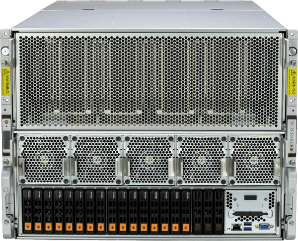
In this setup, each EC2 instance receives an entire H200 via PCIe passthrough and manages its own MIG partitions. This gives each tenant full control over how they slice their GPU — including the ability to run heterogeneous workloads at different partition sizes on the same physical card.
A key consideration for this example is that we do not have access to the router upstream of the X13 host, or knowledge of potentially available IP addresses for the VMs we provision on it. The first step in the Instructions section outlines how we attach our own local IP address range to the bridge on the host, effectively creating a pseudo-airgapped environment - although in this specific case outbound connectivity is still required for remote access to the host, downloading required packages etc, with this configuration it is *not* required for host/EC2 instance communication.
EC2 workload layout
| EC2 Workload | IP | MIG config | Workload | Model |
|---|---|---|---|---|
vm-llama3b | 192.168.10.X | 7 × 1g.18gb | Chat inference × 7 | Llama-3.2-3B-Instruct |
vm-qwen32b | 192.168.10.X | 2 × 3g.71gb | Chat inference × 2 | Qwen2.5-32B-Instruct |
vm-llama70b | 192.168.10.X | 1 × 7g.141gb | Chat inference × 1 | Llama-3.1-70B-FP8 |
vm-yolo | 192.168.10.X | 2 × 3g.71gb | Object detection × 2 | YOLO11x + YOLO11s |
Twelve concurrent inference endpoints in total: 7 fast 3B slots, 2 mid-tier 32B slots, 1 full-GPU 70B slot, and 2 real-time vision streams running side-by-side to compare detection models.
Platform
| Component | Specification |
|---|---|
| Chassis | Supermicro X13 8U GPU System |
| CPUs | 2× Intel Xeon Platinum 8568Y+ (48 cores each, 96 cores / 192 threads total) |
| RAM | 2 TB DDR5-4800 (32× 64 GB SK Hynix DIMMs) |
| Storage | 4× 7.68 TB KIOXIA CD6 NVMe SSDs (30.72 TB raw) |
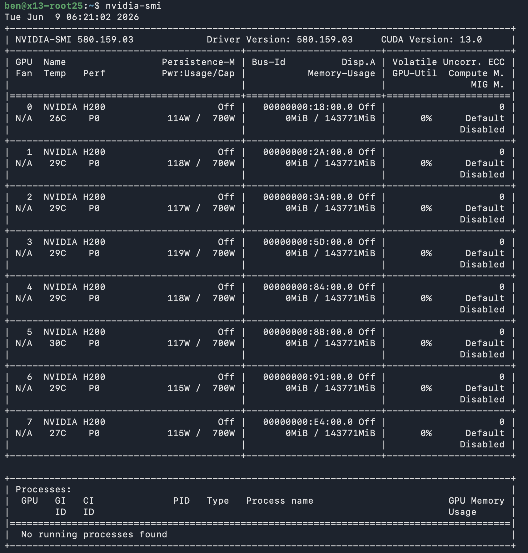
| GPUs | 8× NVIDIA H200 SXM5 (141 GiB HBM3e per GPU, ~1.13 TB total) — 4 used in this demo |
| Host OS | Ubuntu 26.04 LTS |
| Orchestration | Spinifex — EC2-compatible bare-metal API |
| Guest OS | Ubuntu 26.04 LTS |
| GPU partitioning | NVIDIA MIG — managed inside each guest VM |
| Block storage | Predastore — S3-compatible, NVMe-backed |
| Container runtime | Docker |
| Inference runtime | vLLM (vllm-openai image from local registry) |
| Vision runtime | Ultralytics YOLO11 |
Prerequisites
1. Verify GPU visibility on host
Before making any changes, verify that the host can see its GPUs:
Instructions
1. Configure host-local VPC networking
Spinifex utilises bridged networking via OVN. In this example, the remote host exposes only one public IP address, attached to a single physical NIC. Before provisioning Spinifex, we must first ensure that br-wan exists and enslave the physical NIC to it.
Since we have no access to an upstream router or knowledge of available IP address pools, we must also attach our own 192.168.10.0/24 address range to br-wan which will be used by the guest VMs to communicate with the host and each other.
For example:
# /etc/netplan/…
bridges:
  br-wan:
    addresses:
      - 192.168.10.1/24      # VM pool gateway — host-local
      - 198.51.100.10/24     # existing WAN IP — unchanged
    routes:
      - to: default
        via: 198.51.100.1
Then apply with sudo netplan apply. VMs, once provisioned, are reachable from the host at 192.168.10.x. For internet access through the host's WAN interface:
sysctl -w net.ipv4.ip_forward=1
iptables -t nat -A POSTROUTING -s 192.168.10.0/24 -o br-wan -j MASQUERADE
The exact process for this is described in the VPC Networking guide.
2. Install Spinifex
Follow the Single Node Install guide. This process will install Spinifex and start Spinifex services, however spinifex.toml needs to be edited to finalise the changes made to the networking in the previous section, as described in the following section.
3. Configure spinifex.toml and restart services
Edit /etc/spinifex/spinifex.toml to point the external pool and VPCD at the bridge created in step 1:
[network]
external_mode = "pool"

[[network.external_pools]]
name        = "wan"
source      = "static"         # required — no upstream DHCP for this range
range_start = "192.168.10.2"
range_end   = "192.168.10.100"
gateway     = "192.168.10.1"   # second address on br-wan
prefix_len  = 24
dns_servers = ["8.8.8.8"]
Then restart all services:
sudo systemctl start spinifex.target
sudo systemctl status spinifex.target
4. Attach Predastore storage
Spinifex spreads Predastore's object shards across multiple blob nodes using Reed–Solomon encoding for data redundancy. This chassis has four NVMe drives — one for the OS, three dedicated to data — so we back each blob node with its own physical drive, giving us fault-tolerant storage on a single machine — conceptually similar to RAID 5, where data and parity are spread across drives so a single drive failure is recoverable.
A single-node install is one Predastore host running seven nodes, each with a directory named for its node ID under /var/lib/spinifex/predastore/cluster. The three blob nodes are node-2, node-3 and node-4, and they are the ones worth their own drive: the gate keeps no data, and the three meta nodes hold only the Raft log for buckets and the object index.
Confirm drive assignments with lsblk before proceeding, as device names vary between systems.
lsblk   # identify the OS drive and the three data drives

# Stop services so Predastore isn't writing while we relocate its data directories
sudo systemctl stop spinifex.target

# --- Repeat the block below for each data drive (node-2/nvme-1, node-3/nvme-2, node-4/nvme-3) ---

# Mount the physical drive at a stable path
sudo mkdir -p /mnt/nvme-1
sudo mount /dev/nvme1n1 /mnt/nvme-1

# Move the blob node's data off the OS drive onto the physical NVMe
sudo mv /var/lib/spinifex/predastore/cluster/node-2 /mnt/nvme-1/node-2

# Symlink the original path back so Predastore finds its data unchanged
sudo ln -s /mnt/nvme-1/node-2 /var/lib/spinifex/predastore/cluster/node-2

# Persist the mount across reboots
echo "/dev/nvme1n1  /mnt/nvme-1  auto  defaults  0  2" | sudo tee -a /etc/fstab

# --- End of per-drive block ---

sudo systemctl start spinifex.target
Verify the nodes are healthy before proceeding:
export AWS_PROFILE=spinifex

aws s3 ls --endpoint-url https://localhost:8443
# Should return without error (empty bucket list is fine)
5. Enable GPU Passthrough
Spinifex allows GPUs to be utilised by guest VMS via PCIe-passthrough. This can be enabled via sudo spx admin gpu setup. Then, after a reboot, run sudo spx admin gpu enable. The Spinifex banner should update to reflect GPU passthrough state after every step:

6. Import the GPU AMI
The demo uses the standard Spinifex NVIDIA GPU AMI (ubuntu-26.04-nvidia-gpu-x86_64), which includes:
- Ubuntu 26.04 LTS guest image
- NVIDIA server driver (DKMS pre-built against the pinned kernel)
- Docker CE + nvidia-container-toolkit (
--gpussupport enabled at boot) - Python 3 + venv, common utilities (tmux, curl, ffmpeg, etc.)
spx admin images import --name ubuntu-26.04-nvidia-gpu-x86_64Confirm and set the AMI ID:
AMI_ID=$(aws ec2 describe-images \
    --filters "Name=name,Values=ubuntu-26.04-nvidia-gpu-x86_64" \
    --query 'Images[0].ImageId' --output text)
7. Create VPC resources
# Create VPC and subnet
VPC_ID=$(aws ec2 create-vpc --cidr-block 192.168.10.0/24 \
    --query 'Vpc.VpcId' --output text)
SUBNET_ID=$(aws ec2 create-subnet --vpc-id $VPC_ID \
    --cidr-block 192.168.10.0/24 \
    --query 'Subnet.SubnetId' --output text)

# Security group — allow SSH + all vLLM/YOLO ports
SG_ID=$(aws ec2 create-security-group \
    --group-name demo-sg --description "H200 MIG demo" \
    --vpc-id $VPC_ID --query 'GroupId' --output text)

aws ec2 authorize-security-group-ingress --group-id $SG_ID \
    --protocol tcp --port 22 --cidr 0.0.0.0/0
aws ec2 authorize-security-group-ingress --group-id $SG_ID \
--protocol tcp --port 8000-8011 --cidr 0.0.0.0/0# Create SSH key
aws ec2 create-key-pair --key-name spinifex-key \
| jq -r '.KeyMaterial | rtrimstr("\n")' > ~/.ssh/spinifex-key
chmod 600 ~/.ssh/spinifex-key
ssh-keygen -y -f ~/.ssh/spinifex-key > ~/.ssh/spinifex-key.pubVerify:
aws ec2 describe-key-pairs8. Launch the four VMs
Each VM gets a whole H200 via PCIe passthrough. The p5e.4xlarge instance type maps one H200 per VM:
aws ec2 run-instances \
  --image-id $AMI_ID \
  --instance-type p5e.4xlarge \
  --key-name spinifex-key \
  --subnet-id $SUBNET_ID \
  --security-group-ids $SG_ID \
  --count 4
Wait until all four reach running state, then take note of the public IPs assigned to each instance:
aws ec2 describe-instances \
    --query 'Reservations[*].Instances[*].[InstanceId,PublicIpAddress,State.Name]' \
    --output table
9. Enable MIG inside each VM
MIG is enabled inside each guest VM, not on the host. SSH into each VM and enable it:
# Repeat on each VM IP
ssh -i ~/.ssh/spinifex-key ubuntu@<vm-ip>

sudo nvidia-smi -mig 1
nvidia-smi | grep "MIG M."
# Should show: MIG M.  Enabled
10. Create MIG partitions inside each VM
With MIG enabled, we are now able to partition each VM's assigned H200 GPU into several separate GPU instances. This process assigns each GPU slice its own UUID, so each VM goes from seeing one whole GPU to seeing a number of "MIG devices":
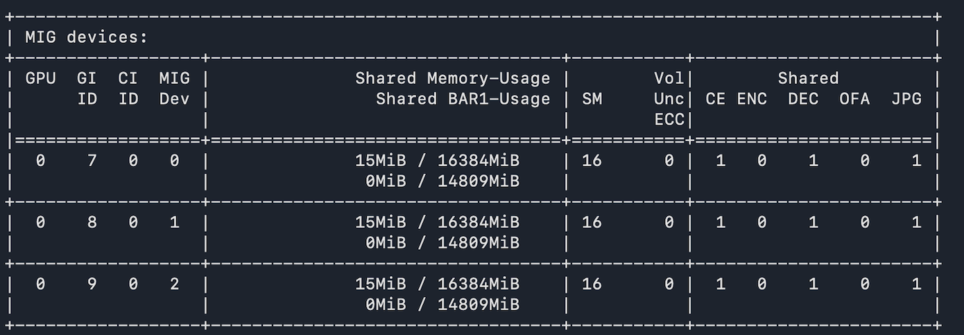
This allows us to run several separate workloads, each assigned to its own GPU instance, on the same physical GPU, and thus utilise more of the overall GPU's resources.
Run nvidia-smi mig -lgip to see the available partition types. MIG profiles are named Xg.Ygb, where:
* X is the number of GPU slices (GPU Instances, or GIs) allocated to the partition. On an H200 there are 7 allocatable GPU slices, so the largest profile is 7g. * Y is the amount of HBM memory allocated to that partition.
Larger profiles also receive proportionally more SMs (Streaming Multiprocessors - analagous to CPU cores), cache, copy engines, encoders/decoders, and other GPU resources.
Thus we partition the GPUs assigned to our VMs as follows:
vm-llama3b — 7 × 1g.18gb (Llama 3B):
sudo nvidia-smi mig -cgi 1g.18gb,1g.18gb,1g.18gb,1g.18gb,1g.18gb,1g.18gb,1g.18gb -C
nvidia-smi -L  # Verify 7 MIG devices
vm-qwen32b — 2 × 3g.71gb (Qwen 32B):
sudo nvidia-smi mig -cgi 3g.71gb,3g.71gb -C
nvidia-smi -L  # Verify 2 MIG devices
vm-llama70b — 1 × 7g.141gb (Llama 70B, full GPU):
sudo nvidia-smi mig -cgi 7g.141gb -C
nvidia-smi -L  # Verify 1 MIG device
vm-yolo — 2 × 3g.71gb (YOLO):
sudo nvidia-smi mig -cgi 3g.71gb,3g.71gb -C
nvidia-smi -L  # Verify 2 MIG devices
Each MIG device gets a UUID of the form MIG-xxxxxxxx-.... These UUIDs are used to pin individual containers to their slice via --gpus "device=<UUID>" (for Docker) or CUDA_VISIBLE_DEVICES=<UUID> (for direct Python processes).
11. Configure Docker to use the local image registry
The vLLM image is served from the host's local Docker registry (192.168.10.1:5000).
Setting up the local registry on the host:
# Configure Docker to trust the local registry address
sudo tee /etc/docker/daemon.json > /dev/null <<'EOF'
{
  "insecure-registries": ["192.168.10.1:5000"]
}
EOF
sudo systemctl restart docker

# Start the registry container, bound to the bridge interface only
docker run -d \
    -p 192.168.10.1:5000:5000 \
    --name registry \
    --restart=always \
    registry:2

# Pull the vLLM image and push it into the local registry
docker pull vllm/vllm-openai:latest
docker tag vllm/vllm-openai:latest 192.168.10.1:5000/vllm-openai:latest
docker push 192.168.10.1:5000/vllm-openai:latest

# Verify the image is available
curl http://192.168.10.1:5000/v2/_catalog
# {"repositories":["vllm-openai"]}
Each VM then needs to trust it as an insecure registry:
# On each VM — vm-yolo uses direct Python, not Docker for YOLO
sudo tee /etc/docker/daemon.json > /dev/null <<'EOF'
{
  "insecure-registries": ["192.168.10.1:5000"]
}
EOF
sudo systemctl restart docker
12. Deploy the LLM workloads
Each LLM is downloaded using the Huggingface CLI onto the respective VM. First install the CLI:
pip install -U "huggingface_hub[cli]"Then download the model and determine its snapshot directory. This directory contains the model’s config.json, tokenizer files, and weight files, and will be used as MODEL_DIR when launching vLLM.
#On vm-llama3b
hf download meta-llama/Llama-3.2-3B-Instruct

MODEL_DIR=$(dirname "$(find ~/.cache/huggingface/hub -path '*Llama-3.2-3B-Instruct*' -name config.json | head -1)")
echo "$MODEL_DIR"

#On vm-qwen32b
hf download Qwen/Qwen2.5-32B-Instruct

MODEL_DIR=$(dirname "$(find ~/.cache/huggingface/hub -path '*Qwen2.5-32B-Instruct*' -name config.json | head -1)")
echo "$MODEL_DIR"

#On vm-llama70b
hf download RedHatAI/Meta-Llama-3.1-70B-Instruct-FP8

MODEL_DIR=$(dirname "$(find ~/.cache/huggingface/hub -path '*Meta-Llama-3.1-70B-Instruct-FP8*' -name config.json | head -1)")
echo "$MODEL_DIR"
Then we run the docker containers as follows:
vm-llama3b — 7 × Llama-3.2-3B-Instruct (one container per MIG slice):
Enumerate the MIG UUIDs and start one vLLM container per slice:
mapfile -t UUIDS < <(nvidia-smi -L | grep -oP 'MIG-[0-9a-f-]+')
for i in "${!UUIDS[@]}"; do
    docker run -d --rm \
        --name "vllm-$i" \
        --gpus "device=${UUIDS[$i]}" \
        --ipc host \
        -p $((8000 + i)):8000 \
        -v "${MODEL_DIR}:/models:ro" \
        192.168.10.1:5000/vllm-openai:latest \
        vllm serve /models \
            --served-model-name llama-3b \
            --dtype bfloat16 \
            --max-model-len 4096 \
            --gpu-memory-utilization 0.90 \
            --port 8000
done
vm-qwen32b — 2 × Qwen2.5-32B-Instruct:
mapfile -t UUIDS < <(nvidia-smi -L | grep -oP 'MIG-[0-9a-f-]+')
for i in "${!UUIDS[@]}"; do
    docker run -d --rm \
        --name "qwen32b-$i" \
        --gpus "device=${UUIDS[$i]}" \
        --ipc host \
        -p $((8000 + i)):8000 \
        -v "${MODEL_DIR}:/models:ro" \
        192.168.10.1:5000/vllm-openai:latest \
        vllm serve /models \
            --served-model-name qwen2.5-32b \
            --dtype bfloat16 \
            --max-model-len 4096 \
            --gpu-memory-utilization 0.90 \
            --port 8000
done
vm-llama70b — Llama-3.1-70B-Instruct-FP8 (full GPU slice):
UUID=$(nvidia-smi -L | grep -oP 'MIG-[0-9a-f-]+' | head -1)
docker run -d --rm \
    --name vllm \
    --gpus "device=${UUID}" \
    --ipc host \
    -p 8000:8000 \
    -v "${MODEL_DIR}:/models:ro" \
    192.168.10.1:5000/vllm-openai:latest \
    vllm serve /models \
        --served-model-name meta-llama-3.1-70b \
        --dtype auto \
        --max-model-len 8192 \
        --gpu-memory-utilization 0.90 \
        --port 8000
13. Deploy YOLO object detection (vm-yolo)
For this demo we built a simple YOLO inference server that runs detection on a looping video file and serves the annotated output as an MJPEG stream. The same script runs twice on vm-yolo — once for YOLO11x (larger, more accurate) and once for YOLO11s (smaller, faster) — each pinned to its own MIG slice and listening on a different port.
The MIG pinning works through CUDA_VISIBLE_DEVICES: setting it to a MIG UUID before launch scopes the process to that slice, and CUDA remaps it to device index 0 inside the process. From the script's perspective it always sees one GPU at index 0 — the MIG boundary is invisible to it. YOLO_MODEL and PORT are what actually differentiate the two instances:
python3 -m venv ~/yolo-venv
~/yolo-venv/bin/pip install ultralytics fastapi "uvicorn[standard]" opencv-python-headless httpx

# Get MIG UUIDs
nvidia-smi -L
# GPU 0: NVIDIA H200 (UUID: GPU-...)
#   MIG 3g.71gb  Device 0: (UUID: MIG-<uuid0>)
#   MIG 3g.71gb  Device 1: (UUID: MIG-<uuid1>)

# YOLO11x on slice 0 — larger model, port 8010
CUDA_VISIBLE_DEVICES=MIG-<uuid0> \
  VIDEO_PATH=<path-to-video> \
  YOLO_MODEL=yolo11x.pt \
  YOLO_DEVICE=0 \
  PORT=8010 \
  ~/yolo-venv/bin/python ~/yolo_stream.py >> ~/yolo-x.log 2>&1 &

# YOLO11s on slice 1 — smaller/faster model, port 8011
CUDA_VISIBLE_DEVICES=MIG-<uuid1> \
  VIDEO_PATH=<path-to-video> \
  YOLO_MODEL=yolo11s.pt \
  YOLO_DEVICE=0 \
  PORT=8011 \
  ~/yolo-venv/bin/python ~/yolo_stream.py >> ~/yolo-s.log 2>&1 &
Each instance exposes a /video endpoint serving a multipart/x-mixed-replace MJPEG stream, consumable directly by browsers and most HTTP clients. YOLO11x (~75 MB) and YOLO11s (~9 MB) weights download automatically on first run from the Ultralytics model hub.
14. Dashboard
We also built a simple host-side dashboard — another FastAPI application that proxies all the VM streams to the browser so only one port on the host needs to be exposed. Each VM endpoint is wired in by address at startup, mapping directly to the IPs assigned in step 8:
http://vm-yolo-IP:8010  →  vm-yolo  YOLO11x MJPEG stream
http://vm-yolo-IP:8011  →  vm-yolo  YOLO11s MJPEG stream
http://vm-llama3b-IP:8000   →  vm-llama3b  vLLM endpoint 0
http://vm-llama3b-IP:8001   →  vm-llama3b  vLLM endpoint 1
... (one entry per endpoint across all three LLM VMs)
The dashboard has two proxy patterns: MJPEG passthrough for the YOLO feeds (forwarding the raw boundary stream from vm-yolo to the browser), and SSE passthrough for the LLM token streams (subscribing to each vLLM endpoint and re-emitting tokens as server-sent events). Both use a reconnect loop so the browser connection stays open if a VM is temporarily unreachable.
The dashboard shows:
- GPU allocation bars for all four EC2 instancess (proportional to MIG slice size)
- Live streaming LLM responses per endpoint, colour-coded by tier
- Side-by-side YOLO11x vs YOLO11s video feeds with FPS and detection counts
The dashboard also displays the overall GPU utilisation, derived as a percentage of maximum power usage. Importantly, it demonstrates how Spinifex combined with NVIDIA's MIG capability enables the deployment of multiple heterogeneous workloads on owned hardware.
15. Teardown
# On vm-yolo:
# Stop YOLO processes
pkill -f yolo_stream.py

# On each LLM instance:
# Stop docker containers

docker stop $(docker ps -q)

# Disable MIG inside each VM before terminating.
sudo nvidia-smi mig -dci
sudo nvidia-smi mig -dgi
sudo nvidia-smi -mig 0

# On the host:
# Terminate all four instances — releases 4× H200 back to the Spinifex pool
aws ec2 terminate-instances --instance-ids \
    $(aws ec2 describe-instances \
        --filters "Name=instance-state-name,Values=running" \
        --query 'Reservations[*].Instances[*].InstanceId' \
        --output text)
The four H200s are immediately returned to the host GPU pool once the instances terminate, ready for reallocation.
16. Conclusion
This document highlights how Spinifex can turn a single bare-metal chassis into a multi-tenant AI serving platform. Spinifex utilises the flexibility of PCIe passthrough combined with NVIDIA's MIG capability to allocate GPU resources in whichever configuration is required by the workload/s. This flexibility and fine-grain control ensures maximum GPU utilisation.
Importantly, it does so with standard aws ec2 CLI calls — run-instances, describe-instances, terminate-instances — against Spinifex's EC2-compatible endpoint. Teams already operating AWS infrastructure can point their existing tooling at a Spinifex node with a single profile change, against GPUs that sit in their own rack.